A few months ago, I bought an entry-level CNC router from a local supplier, knowing full well that I would probably need to modify it extensively. The price of the machine was right, and in case I decide to build a better one on my own, this machine would be a good starting point to learn how all the parts are connected together.
The machine performed OK as long as I didn’t push it hard. I added drag chains to the Y-axis to prevent the step motor cables from moving all over the place while the machine was running. I also added a dust boot which was not only essential for dust extraction, but also freed me from standing right next to the machine holding a vacuum hose while it was running.
After these modifications, connecting a simple height probe that would be used to automatically calculate the distance of the router bit to the waste board seemed easy enough – just two wires connected to the control board located inside the CNC router control box. But, try as I might, I couldn’t get my hands to the red control board even after removing some of the cabling. It was very cramped inside. I also needed to reduce the current to the Y axis motors (they got too hot), but I couldn’t access the jumpers on the step motor drivers either. There were other things that I wasn’t happy with the control box – there were no jacks outside the box to connect cables. All cables went straight inside through bushings.
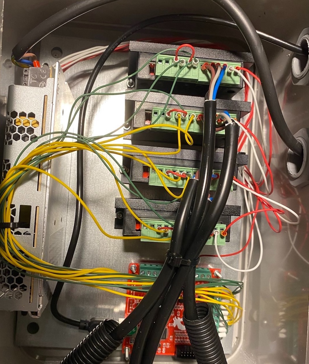 Inside the original cramped CNC router control box.
So, I thought it wouldn’t be too hard to buy a bigger box and move everything from the old box to the new one, making a few improvements along the way. A CNC router control box is relatively simple to make. It consists of a power supply, step motor drivers and a control board. I replaced the generic brand 12V power supply with a Mean Well 24V power supply I had lying around. The extra voltage should help the motors generate more torque at higher speeds.
I changed the component layout so that the control board’s USB input could be accessed directly from the outside. I also placed the step motor drivers between the power supply and control board to separate signal wires coming from the control board and power wires coming from the power supply as much as possible. Finally, I added cable ducts with slits to keep the wiring neat. Can’t recommend these ducts enough – they make wire management very easy.
The pictures below show the testing of the components outside the box, and a close-up view of the step motor driver wiring.
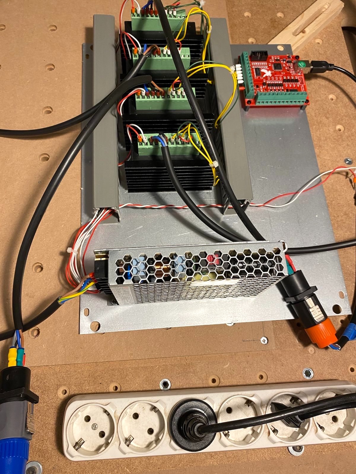 The new electronics layout was tested outside the box.
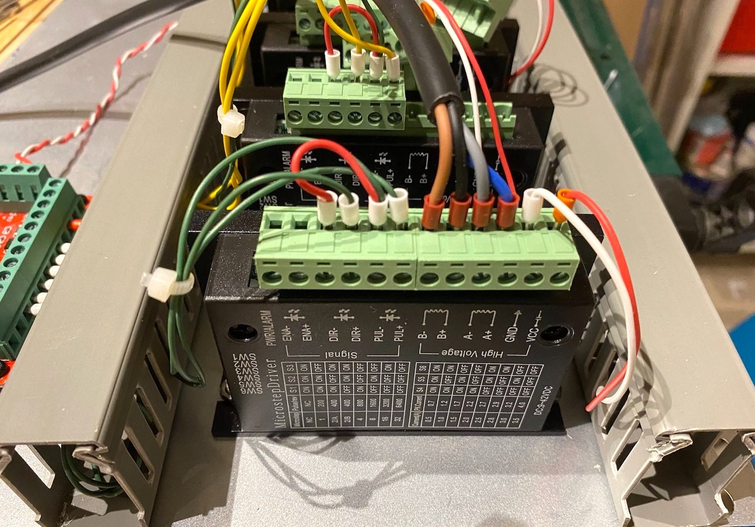 Signal wires come from one side and power wires come from the other side through wire ducts.
For outside connections, I used 4-pole Speakon connectors for step motor cables, and 3-pole XLR connectors for things like height probes and limit switches. These connectors are normally used in professional audio, but I really like the easy locking mechanism of these types of audio connectors.
In the picture below, only the AC power socket and the Speakon jacks are installed. With the “eyes and mouth”, the box kind of looks cute though, don’t you think? :)
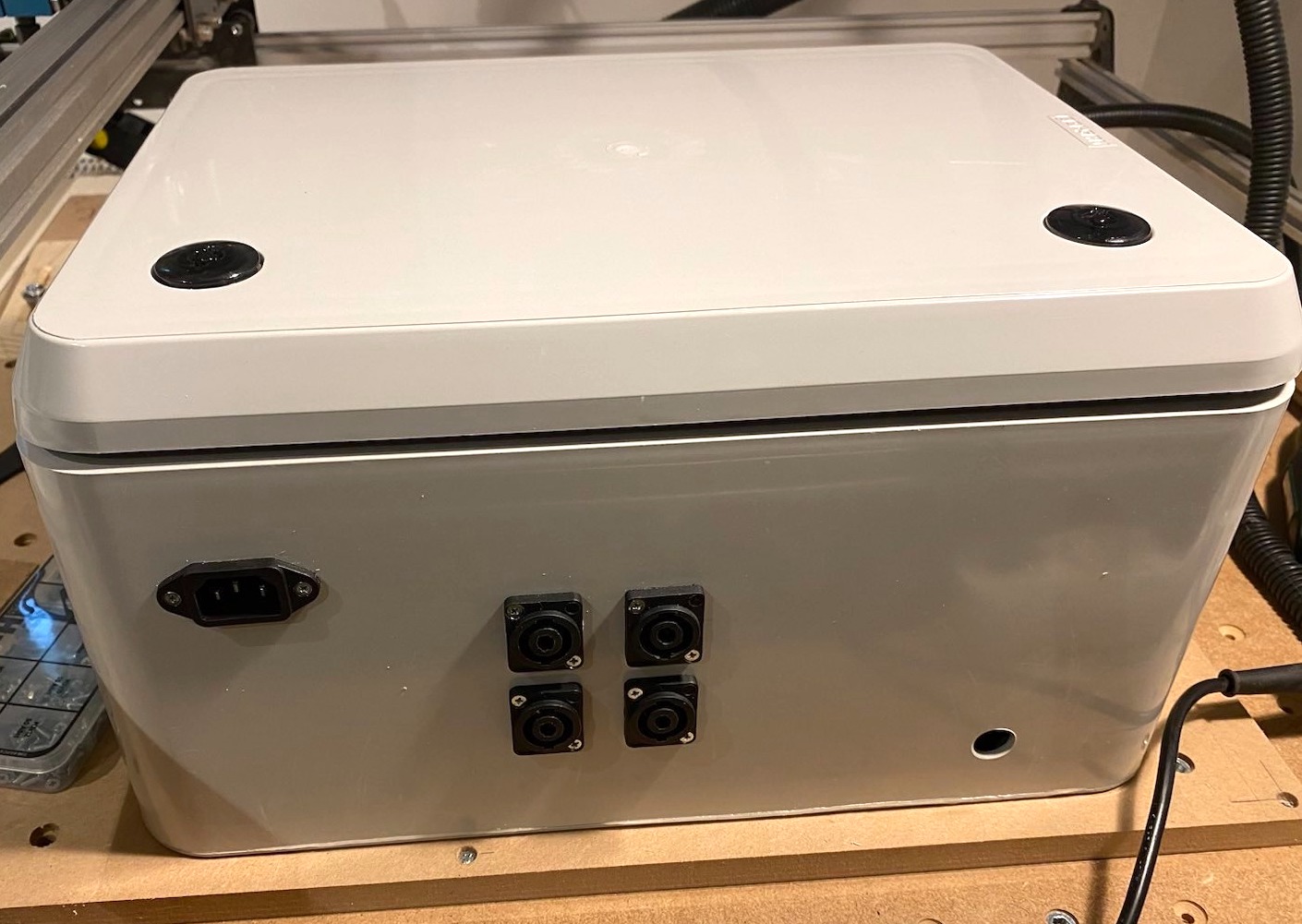 Outside view of the new CNC router control box with Speakon jacks installed.
The picture below shows the components installed in the box. There’s plenty of space now for future expansion. It’s probably a good idea to install a fan to keep the components cool especially if the machine is expected to run long hours.
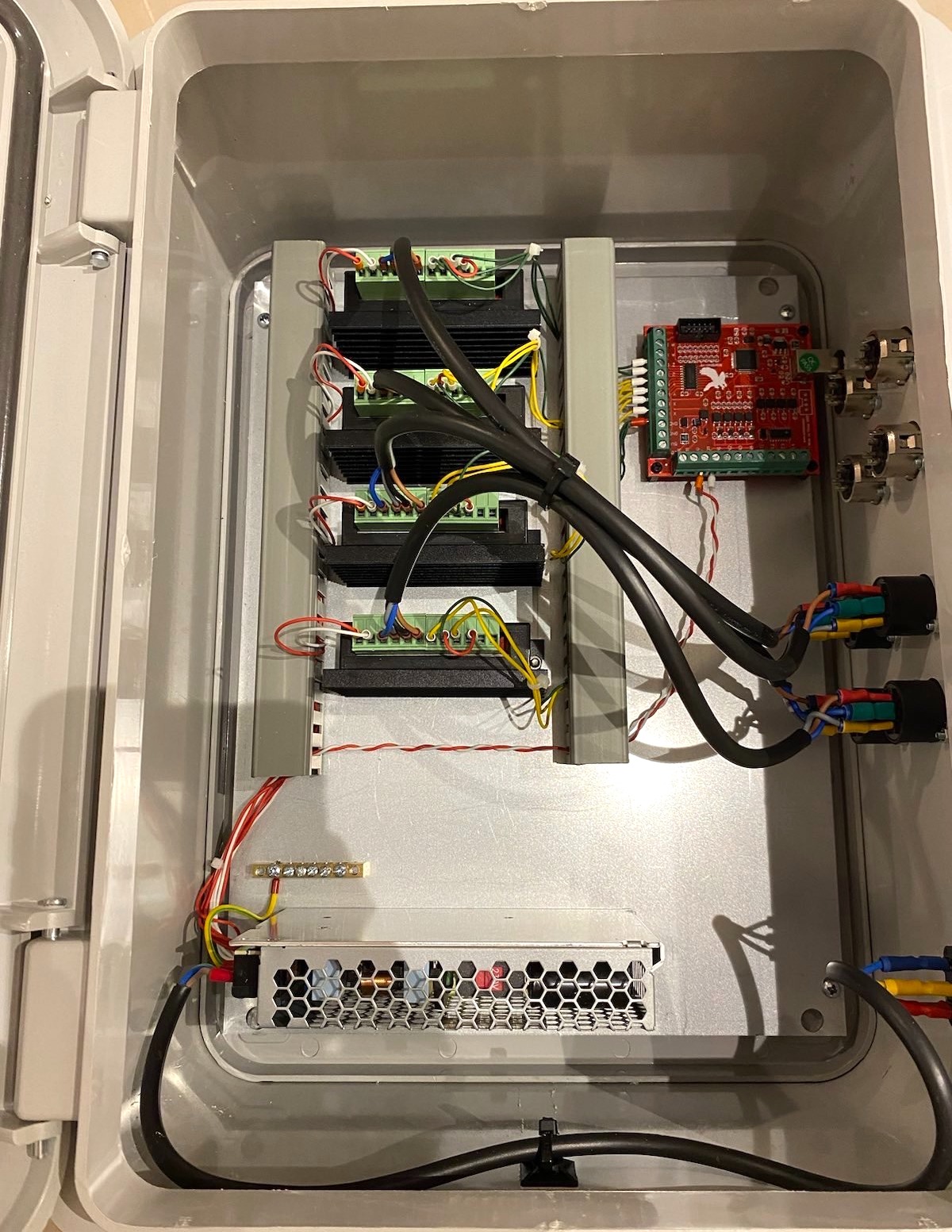 Inside the new CNC router control box. No bushings! :)
Tools of the trade: Wire stripper, crimpers, and a cordless drill with the necessary bits. I especially like the look of the big step bit installed in the cordless drill. Looks like a ray gun :) You can buy the cheapest step drill bit you can find. They are perfectly adequate for drilling plastic, which is all I needed here.
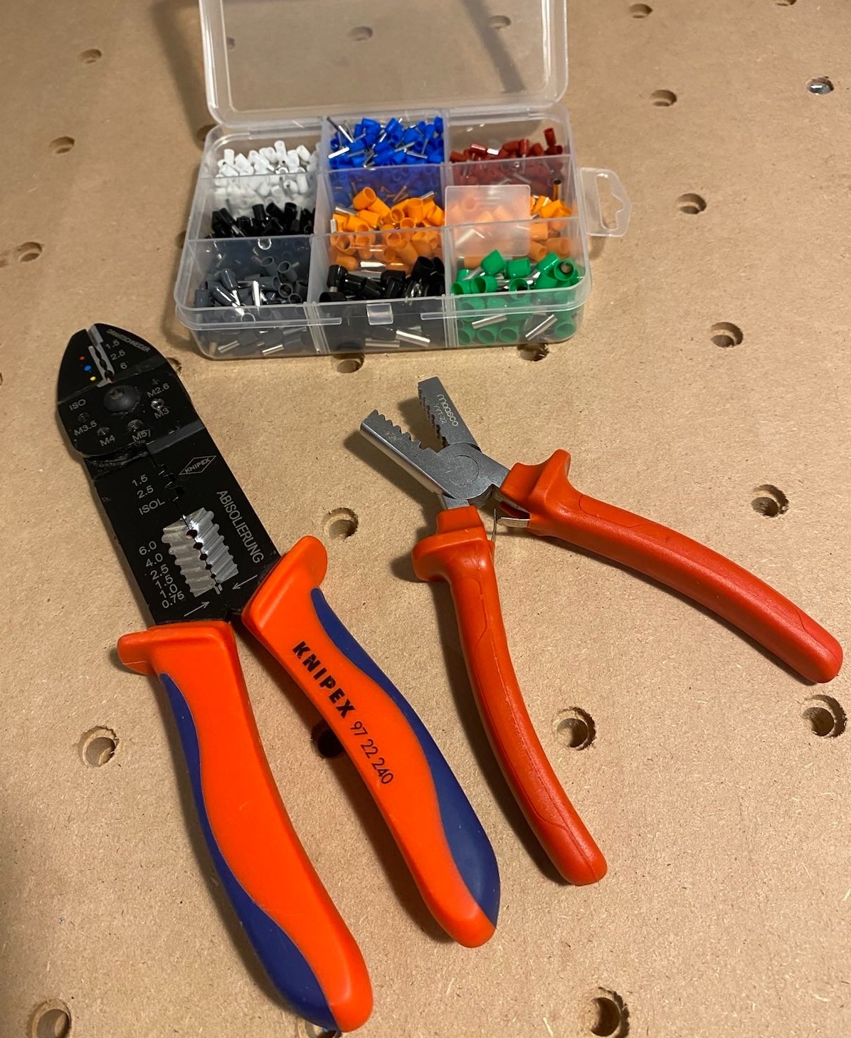 Wire crimpers.
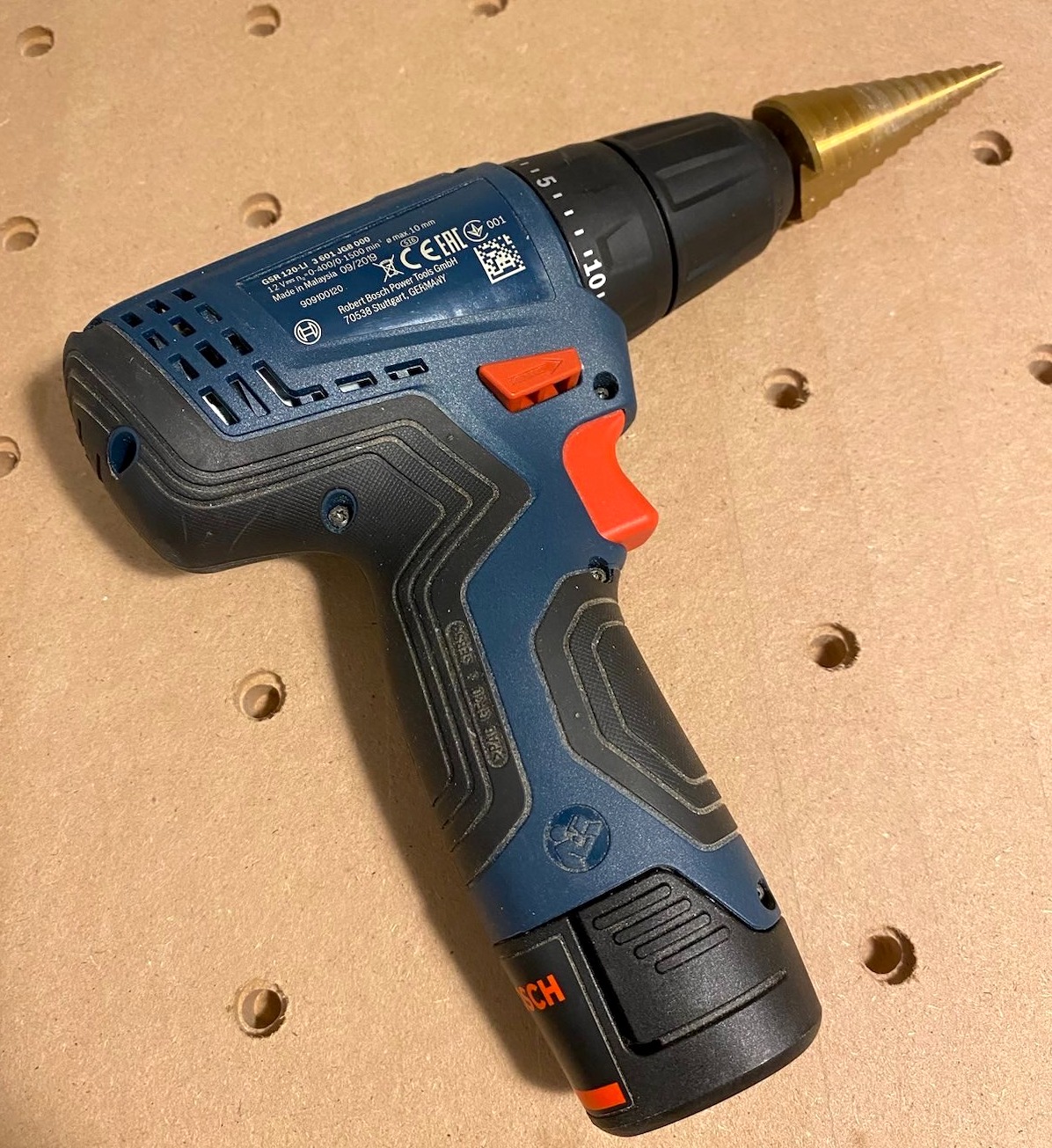 Step drill bit is great for circular cutouts on plastic.
Finally, the finished CNC router control box with four step motor connectors and one height probe connected.
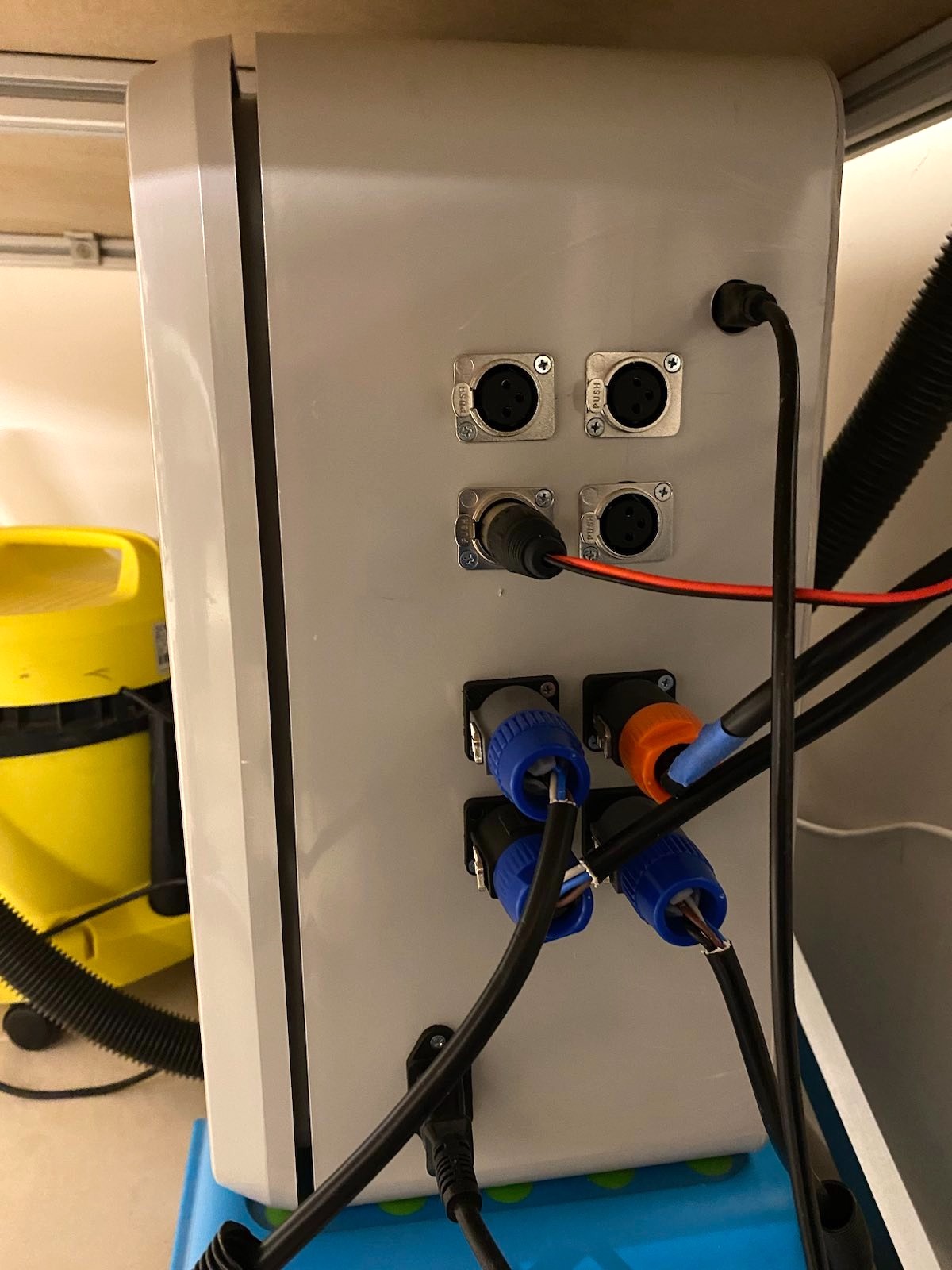 The new CNC router control box standing under the CNC router table.
Disclaimer: Working on electronics connected to AC power can kill you. If you don’t know what you are doing, please don’t. Also, keep in mind that I’m a hobbyist, but I did consult professionals including an electrical engineer friend for my CNC control box work.
Related: